Jul 24, 2026Industry News
Complete Guide to OPGW Fittings and Accessories
Learn about OPGW fittings and accessories, including tension sets, suspension sets, vibration dampers, grounding wires, splice closures and selection requirements.
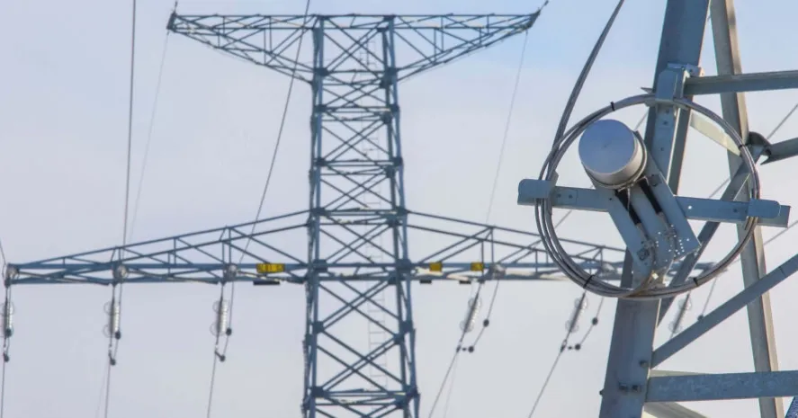
Optical Ground Wire, commonly known as OPGW, combines two important functions in one overhead cable. It acts as a shield wire that helps protect power transmission lines from lightning, while the optical fibers inside the cable provide a reliable communication channel for protection, control, monitoring and data transmission.
OPGW is normally installed at the top of transmission towers, where it is exposed to wind, vibration, mechanical tension, lightning, short-circuit current, temperature changes and environmental corrosion. IEEE 1138 covers the mechanical, electrical, optical and environmental performance requirements of OPGW, while IEC 60794-4-10 specifies construction and performance requirements for OPGW used for lightning protection and communication purposes.
However, the cable alone cannot provide a reliable OPGW system. The correct fittings and accessories are needed to support, terminate, protect, ground and connect the cable throughout the transmission line.
This guide explains the main types of OPGW fittings, their functions and the key factors engineers and buyers should consider when selecting them.
What Are OPGW Fittings?
OPGW fittings are specially designed hardware components used to attach an OPGW cable to transmission towers or poles.
Unlike ordinary overhead ground wire fittings, OPGW fittings must hold the cable securely without placing excessive compression, bending or concentrated stress on the optical fibers inside it. Improperly selected hardware may damage the cable structure, increase optical attenuation or cause the cable to slip under mechanical load.
IEEE 1591.1 establishes performance requirements, testing procedures and acceptance criteria for hardware used with OPGW systems. These requirements address mechanical, electrical, optical and environmental performance during installation and service.
A complete OPGW hardware system commonly includes:
- Tension or dead-end assemblies
- Suspension assemblies
- Vibration dampers
- Grounding wire assemblies
- Splice closures
- Downlead clamps
- Cable storage brackets
- Tower attachment hardware
- Repair fittings and protective rods
Each component performs a different function and must be selected according to the cable and line design.
1. OPGW Tension Sets
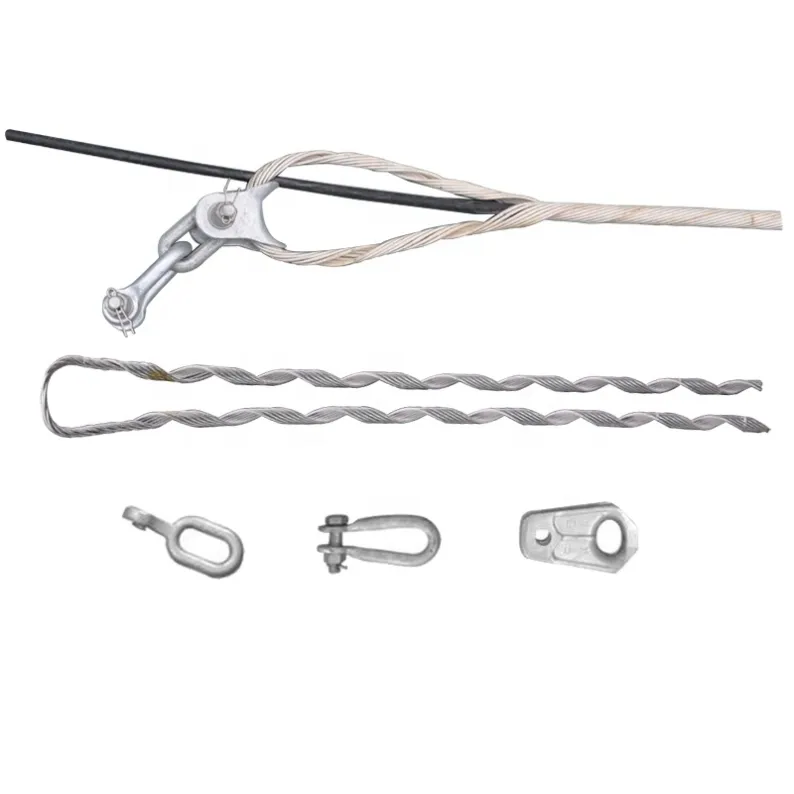
An OPGW tension set, also called a dead-end set or strain set, is used to terminate the cable and transfer its tensile load to a tension tower, terminal tower or angle tower.
Tension sets are commonly installed at:
- Line terminals
- Major angle towers
- Sectioning towers
- OPGW joint locations
- Long-span crossings
- Locations where cable tension must be isolated
A typical formed-wire OPGW tension set may include:
- Structural reinforcing rods
- Outer dead-end rods
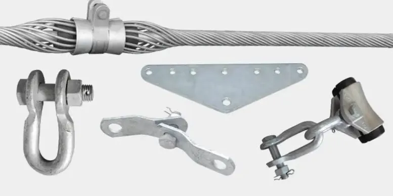
- Thimble clevis
- Extension link
- Anchor shackle
- Grounding connection
- Installation accessories
The inner reinforcing rods distribute mechanical pressure over a longer section of cable. The outer dead-end rods grip the reinforced cable and transfer the axial load to the tower attachment.
This load distribution is critical because concentrated clamping force could deform the metallic strands or damage the optical unit inside the OPGW.
Commercial OPGW dead-end systems are designed to distribute axial and compressive loads over a relatively large cable surface. Their holding strength can depend on the OPGW construction, strand materials, cable diameter, number of layers and lay direction.
Key selection factors
When selecting an OPGW tension set, confirm:
- OPGW outside diameter
- Rated tensile strength
- Maximum working tension
- Cable strand construction
- Left-hand or right-hand lay direction
- Tower attachment dimensions
- Required holding strength
- Short-circuit current requirement
- Environmental and corrosion conditions
A tension set should never be selected only by cable diameter. Two OPGW cables with the same diameter may have different strand materials, tensile strengths and internal constructions.
2. OPGW Suspension Sets
OPGW suspension sets support the cable at tangent towers or towers with relatively small line angles.
Their purpose is not simply to hold the cable. A properly designed suspension system must also reduce bending stress, compression and wear at the support point.
A typical OPGW suspension set includes:
- Structural reinforcing rods
- Outer protective rods
- Elastomer or rubber inserts
- Suspension housing
- Clevis or link fittings
- Grounding connection
- Shackles and tower attachment hardware
The reinforcing rods increase the effective bending radius and distribute the load over a longer cable section. The elastomer inserts cushion the cable and help reduce contact pressure.
OPGW suspension products are designed to reduce compression, clamping and bending stress while limiting the effects of wind-induced cable movement, including aeolian vibration, galloping and wind sway.
Single and double suspension sets
A single suspension set is normally used on tangent towers and smaller line angles. Double suspension assemblies may be required where the line angle, vertical load or mechanical condition exceeds the capacity of a single assembly.
The permitted line angle varies by product design. For example, some commercial suspension systems recommend a single assembly for line angles up to approximately 30 degrees and a double assembly for larger angles. This value should not be treated as universal; the project engineer must verify the supplier’s tested design and the actual line conditions.
Important information for selection
The supplier may need:
- Cable diameter
- Cable weight per unit length
- Rated tensile strength
- Maximum span
- Line angle
- Vertical and transverse loads
- Cable lay direction
- Tower attachment arrangement
- Expected vibration conditions
3. Vibration Dampers
Wind can produce high-frequency, low-amplitude movement known as aeolian vibration. Over time, repeated bending near clamps and support points may cause strand fatigue, wear or damage to the cable.
Vibration dampers absorb and dissipate part of this vibration energy before it creates harmful stress.
Common OPGW vibration-control products include:
- Stockbridge vibration dampers
- Spiral vibration dampers
- Special dampers installed over reinforcing rods
- Structural rods used beneath damper clamps
IEC 60794-1-119:2025 defines aeolian-vibration test procedures for aerial optical cables, including OPGW, ADSS and OPPC cables. The test is intended to establish consistent mechanical performance requirements under vibration exposure.
Stockbridge dampers
A Stockbridge damper generally consists of a messenger cable with weights at both ends and a central clamp. When the cable vibrates, the damper moves at a different frequency and dissipates vibration energy.
The damper model, quantity and installation position should be calculated according to:
- Cable diameter
- Cable mass
- Cable tension
- Span length
- Terrain
- Wind conditions
- Damper frequency range
- Suspension or dead-end configuration
Spiral vibration dampers
Spiral dampers are helically formed products installed around the cable. They are commonly used on fiber-optic cables and smaller-diameter conductors.
They can provide a simple vibration-control solution, but their application range must be matched to the cable diameter and project conditions. Commercial spiral vibration dampers are sized to create the required interaction between the damper and cable.
Vibration damper placement should follow an approved installation drawing. Installing a damper too close to or too far from the support point may reduce its effectiveness.
4. OPGW Grounding Wire Assemblies
Because OPGW functions as an overhead ground wire, it must be electrically connected to the transmission tower grounding system.
A grounding assembly normally includes:
- Aluminum or copper grounding conductor
- Compression terminals or lugs
- Grounding bolts
- Current-transfer tabs
- Tower connection hardware
Some OPGW tension and suspension fittings include an integrated grounding point. This allows current to transfer directly from the OPGW to the grounding lead instead of passing through unsuitable components in the hardware assembly.
Grounding requirements
The grounding conductor must be selected according to:
- Maximum fault current
- Short-circuit duration
- Grounding system design
- Conductor material
- Terminal material
- Connection resistance
- Environmental conditions
For installations with higher fault-current requirements, a larger grounding conductor, higher-rated current-transfer component or additional grounding lead may be needed.
Material compatibility is also important. Direct contact between dissimilar metals in wet or coastal environments can create galvanic corrosion. Suitable terminals, interface materials and protective measures should therefore be specified.
5. OPGW Splice Closures
An OPGW splice closure protects optical-fiber joints from moisture, dust, vibration, mechanical damage and environmental exposure.
Splice closures are commonly installed on joint towers where two OPGW cable sections are connected. They may also connect OPGW to a separate downlead or underground optical cable.
A typical closure system includes:
- Closure body
- Cable entry ports
- Sealing components
- Cable strain-relief hardware
- Fiber splice trays
- Fiber-management accessories
- Tower mounting brackets
- Grounding components where required
The closure must provide adequate space for fiber preparation, splicing, routing and future maintenance.
Commercial OPGW closures are available with different splice capacities and cable-entry arrangements. Some closure systems are designed for either OPGW or ADSS cables and include dedicated strain-relief kits for securing the incoming cable.
Important selection factors
Buyers should confirm:
- Fiber count
- Required splice capacity
- Number of cable ports
- Cable diameter
- Cable construction
- Splice type
- Required spare-fiber storage
- Tower mounting arrangement
- Sealing and ingress-protection requirements
- Operating temperature
- Corrosion resistance
- Future expansion requirements
The closure must also allow technicians to maintain the minimum fiber-bending radius specified for the optical fiber and cable design.
6. Downlead Clamps
At a splice tower, the OPGW cable normally leaves the overhead position and runs down the tower to the splice closure. Downlead clamps secure this section of cable to the tower.
The clamps must hold the cable firmly without crushing, flattening or creating a sharp bend.
Common designs use:
- Elastomer inserts
- Cushion materials
- Adjustable brackets
- Stainless-steel straps
- Bolted tower attachments
- Multiple cable-clamping positions
Purpose-designed downlead cushions secure OPGW or ADSS downleads while minimizing concentrated compression on the cable.
Downlead clamps should be spaced according to the project drawing, tower geometry, cable weight and wind exposure. Insufficient clamps may allow excessive cable movement, while excessive tightening may damage the cable.
7. Cable Storage Assemblies
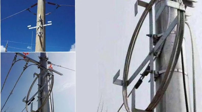
Extra OPGW cable is often stored on the tower near the splice closure to provide sufficient length for initial installation and future maintenance.
Cable storage systems may include:
- Storage brackets
- Cable support arms
- Cushion clamps
- Tower mounting bolts
- Stainless-steel straps
- Cable-retaining clips
The storage loop must maintain an acceptable bending radius. The cable should not be folded, twisted or forced into a loop smaller than the cable manufacturer’s recommendation.
The storage system should also keep the cable clear of climbing routes, sharp tower edges and other equipment.
8. Tower Attachment Hardware
OPGW assemblies require mechanical fittings to connect them to the tower structure.
Depending on the line design, these may include:
- Anchor shackles
- Clevis fittings
- Extension links
- Yoke plates
- U-bolts
- Eye bolts
- Tower brackets
- Adjustment links
- Chain links
The attachment hardware must have sufficient mechanical strength for the maximum design load, including appropriate safety factors.
Dimensions must also be checked carefully. A technically correct OPGW tension set may still be unsuitable if the shackle, clevis or attachment hole does not match the tower plate.
The complete load path—from the OPGW cable through the formed-wire assembly and connection hardware to the tower—should be reviewed as one system.
9. OPGW Repair Fittings
OPGW may be damaged during installation, maintenance work, lightning events or external impact.
The repair method depends on:
- Number of damaged outer strands
- Depth and location of the damage
- Remaining mechanical strength
- Electrical conductivity
- Condition of the optical unit
- Optical attenuation
- Utility maintenance rules
Minor external strand damage may sometimes be repaired using armor rods or repair rods. More serious damage may require a repair splice, new closure or replacement cable section.
A visible surface defect does not always show whether the optical unit has been affected. Optical testing, such as OTDR measurement, may therefore be required before approving the repair.
Repair products should not be used to hide damage that has reduced the cable below the required mechanical, electrical or optical performance.
How to Select the Correct OPGW Fittings
A reliable quotation requires more than an OPGW diameter.
Before requesting OPGW fittings, buyers should provide the following information.
OPGW cable information
- Cable manufacturer and model
- Outside diameter
- Cross-sectional construction
- Strand materials
- Number of strand layers
- Rated tensile strength
- Maximum working tension
- Cable weight
- Lay direction
- Short-circuit rating
- Fiber count
- Cable drawing or datasheet
Transmission-line information
- Voltage level
- Maximum span
- Normal span
- Line angle
- Tower type
- Maximum vertical load
- Maximum transverse load
- Environmental conditions
- Expected vibration level
- Required safety factors
Hardware requirements
- Tension-set quantity
- Suspension-set quantity
- Damper type and quantity
- Grounding-lead specification
- Splice-closure capacity
- Downlead-clamp quantity
- Cable-storage arrangement
- Tower attachment dimensions
- Required standards
- Inspection and testing requirements
Without this information, a supplier may be able to provide only a preliminary recommendation.
Important Tests for OPGW and Its Hardware
Depending on the project specification, qualification and acceptance testing may cover:
- Tensile performance
- Cable-to-hardware holding strength
- Slip performance
- Vibration endurance
- Galloping performance
- Optical attenuation
- Short-circuit current
- Lightning performance
- Temperature cycling
- Corrosion resistance
- Salt-spray exposure
- Mechanical fatigue
- Grounding-current transfer
IEC 60794-1-401 addresses short-circuit testing of OPGW and OPPC, while IEC 60794-1-402 covers tests used to evaluate the effect of lightning strikes. IEC 60794-1-220 specifies controlled salt-atmosphere testing for metallic aerial optical cables such as OPGW.
The exact test program should be agreed before production because different utilities and projects may apply different acceptance criteria.
Common OPGW Fittings Procurement Mistakes
Selecting fittings only by cable diameter
Diameter is important, but it is not enough. Cable strength, strand construction, lay direction and metallic materials also affect hardware performance.
Using ordinary conductor clamps
OPGW contains sensitive optical elements. Hardware designed for a conventional conductor or ground wire may create excessive compression or bending stress.
Ignoring the cable lay direction
Preformed rods are manufactured for a particular lay direction. Using the wrong design can affect installation and holding performance.
Failing to confirm the tower interface
Shackles, clevises, links and brackets must fit the tower attachment holes and available installation space.
Ordering dampers without placement calculations
The correct damper may perform poorly when installed in the wrong position or quantity.
Undersizing the grounding lead
Grounding components should be selected based on the system fault-current requirement, not simply by copying a standard cable size from another project.
Mixing unverified components
OPGW hardware should operate as an integrated system. Combining tension rods, structural rods, grounding parts and attachment hardware from unrelated designs may change load distribution and electrical performance.
Ignoring corrosion compatibility
Coastal, industrial, tropical and polluted environments may require additional attention to galvanizing, aluminum components, stainless-steel parts and contact between dissimilar metals.
Supplier Evaluation Checklist
Before selecting an OPGW fittings supplier, buyers should evaluate whether the supplier can:
- Review the complete OPGW cable datasheet
- Recommend products based on mechanical and electrical requirements
- Provide detailed assembly drawings
- Confirm cable diameter and lay direction
- State the tested holding strength
- Provide installation instructions
- Supply complete kits rather than incomplete components
- Offer material and coating documentation
- Provide type-test or qualification reports when required
- Maintain batch identification and traceability
- Support pre-shipment inspection
- Produce customized tower attachment hardware
- Pack and label each assembly clearly
A lower unit price provides little benefit if the hardware does not match the cable or if missing components delay installation.
Packaging and Delivery
OPGW projects normally involve many similar-looking components. Clear packaging is therefore essential.
Each package should identify:
- Project name
- Product description
- Part number
- Cable diameter range
- Tower or installation position
- Assembly quantity
- Box number
- Gross and net weight
- Installation drawing reference
Small components such as bolts, shackles, pins and grounding terminals should be packed securely and listed on the packing document.
For large projects, organizing the hardware by tower number or installation section can reduce sorting time and prevent missing parts at the construction site.
Conclusion
OPGW fittings are critical parts of an overhead optical communication and grounding system. Their performance affects not only the mechanical security of the cable but also its electrical continuity and optical reliability.
A complete OPGW hardware package may include tension sets, suspension sets, vibration dampers, grounding leads, splice closures, downlead clamps, storage brackets and tower attachment fittings.
The correct selection must be based on the actual OPGW construction, cable diameter, rated tensile strength, lay direction, span, line angle, fault-current requirement and environmental conditions.
SENOTECH supplies OPGW fittings and accessories for transmission-line and communication projects. Products can be supplied as individual components or coordinated assemblies according to cable data, project drawings and technical requirements.